
SP Tubular Poles: How to Read the 410 SP Designation, Load and Planting Depth
Written by the Surya Traders team. Category: Tubular Poles.
Ask three suppliers for an “8 m tubular pole” and you may get three different poles. They can match on height and still differ in diameter, wall thickness, load capacity and planting depth. For swaged poles, the way out is the SP designation: a short code that points to one row of a standard table in which every dimension and load is defined.
This guide explains how to read that code. You will see what an SP (swaged) tubular pole is, what the numbers mean, how loads and planting depth work, and how to choose a designation without guessing. It is written for contractors, electrical consultants, utilities, municipal buyers and anyone ordering poles for lighting or overhead lines.
Quick answer: do not order by height. Order by designation, state the load and the point where it acts, confirm the planting depth, and ask for the coating and test documents in writing.
1. What Is an SP (Swaged) Tubular Pole?
A swaged tubular pole is built from steel tubes of decreasing diameter. The largest tube forms the bottom. Smaller tubes are joined above it by swaging, a mechanical process that fits one tube into the next. The result is a stepped, tapering pole that is strong at the base, where bending is greatest, and lighter at the top.
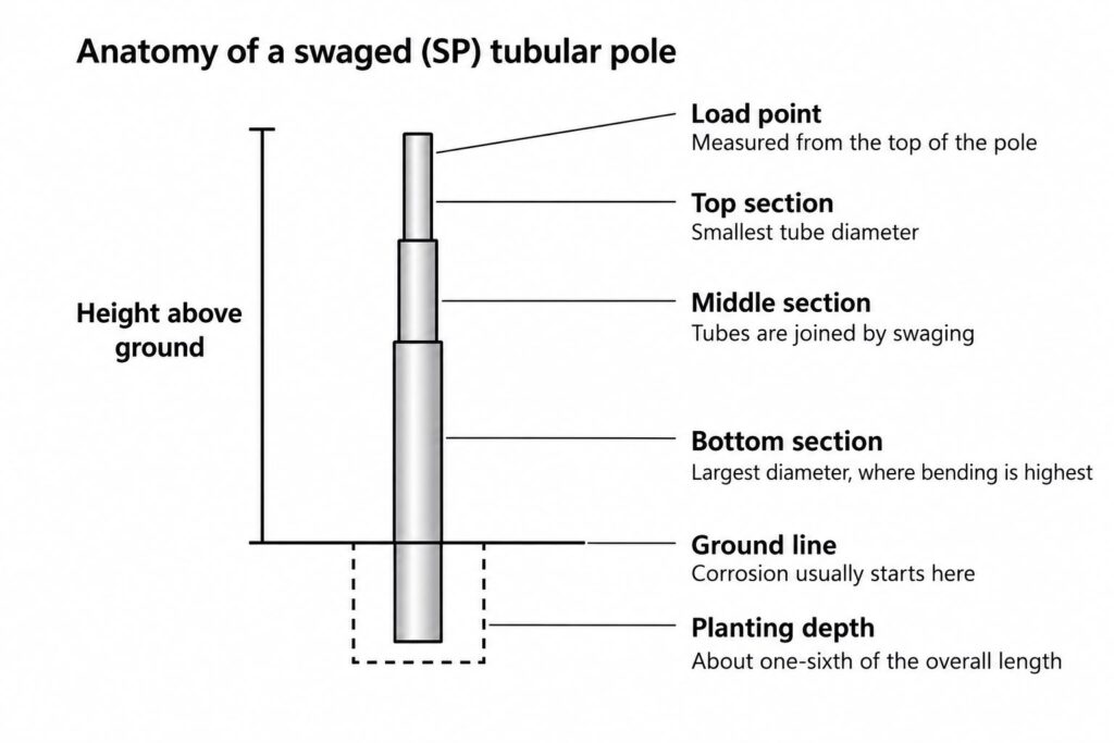
In India these poles are covered by IS 2713, the BIS standard for tubular steel poles for overhead power lines. Part 1 gives the general requirements. Part 2 covers stepped and swaged poles made from steel of 410 MPa minimum tensile strength, and Part 3 covers the 540 MPa class. You can read the scope in the IS 2713 preview on the BIS website.
“SP” stands for swaged pole, and “410” refers to the steel class. That is why you will see designations such as 410 SP-17 or 410 SP-43.
Although IS 2713 was written for power lines, the same type of pole is widely used for street lighting and similar jobs. Standards are revised or withdrawn from time to time, so confirm the current status with BIS or your consultant before you quote a clause in a tender.
2. How to Read an SP Designation
A designation such as 410 SP-23 is not just a name. It points to one row in a table, and that row fixes all of these:
- Overall length and planting depth
- Height above ground
- Length of the bottom, middle and top sections
- Outside diameter and wall thickness of each section
- Approximate weight
- Breaking, working and crippling loads, and the point where the load acts
Two poles of the same length can have different designations. The difference lies in the tube sizes, and the tube sizes decide how much load the pole can carry. A pole with larger diameters and thicker walls generally carries more, even at the same height.
That is the main reason to quote the designation and not just the height. “8.5 m pole” describes a length. “410 SP-23” describes a pole.
3. SP Tubular Pole Table
The table below shows four designations in the 8 m to 10 m range. The values are taken from manufacturers’ published specification sheets for IS 2713 Part 2 poles, so treat them as a guide and confirm them against the standard and your supplier’s drawing before ordering.
| 410 SP |
Overall Length (m) |
Planting Depth (m) |
Height Above Ground (m) |
Sections B / M / T (m) |
Bottom OD × T (mm) |
Middle OD × T (mm) |
Top OD × T (mm) |
Approx. Weight (kg) |
|---|---|---|---|---|---|---|---|---|
| SP-1 | 7.00 | 1.25 | 5.75 | 4.00 / 1.50 / 1.50 | 114.3 × 3.65 | 88.9 × 3.25 | 76.1 × 3.25 | 62 |
| SP-2 | 7.00 | 1.25 | 5.75 | 4.00 / 1.50 / 1.50 | 114.3 × 4.50 | 88.9 × 4.05 | 76.1 × 3.25 | 73 |
| SP-3 | 7.00 | 1.25 | 5.75 | 4.00 / 1.50 / 1.50 | 114.3 × 5.40 | 88.9 × 4.85 | 76.1 × 3.25 | 85 |
| SP-4 | 7.50 | 1.25 | 6.25 | 4.50 / 1.50 / 1.50 | 114.3 × 3.65 | 88.9 × 3.25 | 76.1 × 3.25 | 67 |
| SP-5 | 7.50 | 1.25 | 6.25 | 4.50 / 1.50 / 1.50 | 114.3 × 4.50 | 88.9 × 4.05 | 76.1 × 3.25 | 79 |
| SP-10 | 8.00 | 1.50 | 6.50 | 4.50 / 1.75 / 1.75 | 114.3 × 3.65 | 88.9 × 3.25 | 76.1 × 3.25 | 70 |
| SP-12 | 8.00 | 1.50 | 6.50 | 4.50 / 1.75 / 1.75 | 114.3 × 5.40 | 88.9 × 4.85 | 76.1 × 3.25 | 97 |
| SP-15 | 8.00 | 1.50 | 6.50 | 4.50 / 1.75 / 1.75 | 139.7 × 5.40 | 114.3 × 4.50 | 88.9 × 3.25 | 119 |
| SP-18 | 8.50 | 1.50 | 7.00 | 5.00 / 1.75 / 1.75 | 114.3 × 5.40 | 88.9 × 4.85 | 76.1 × 3.25 | 104 |
| SP-21 | 8.50 | 1.50 | 7.00 | 5.00 / 1.75 / 1.75 | 139.7 × 5.40 | 114.3 × 4.50 | 88.9 × 3.25 | 129 |
| SP-24 | 8.50 | 1.50 | 7.00 | 5.00 / 1.75 / 1.75 | 165.1 × 5.40 | 139.7 × 4.50 | 114.3 × 3.65 | 158 |
| SP-27 | 9.00 | 1.50 | 7.50 | 5.00 / 2.00 / 2.00 | 114.3 × 5.40 | 88.9 × 4.85 | 76.1 × 3.25 | 108 |
| SP-30 | 9.00 | 1.50 | 7.50 | 5.00 / 2.00 / 2.00 | 139.7 × 5.40 | 114.3 × 4.50 | 88.9 × 3.25 | 133 |
| SP-33 | 9.00 | 1.50 | 7.50 | 5.00 / 2.00 / 2.00 | 165.1 × 5.40 | 139.7 × 4.50 | 114.3 × 3.65 | 164 |
| SP-39 | 9.50 | 1.80 | 7.70 | 5.00 / 2.25 / 2.25 | 165.1 × 5.40 | 139.7 × 4.50 | 114.3 × 3.65 | 170 |
| SP-45 | 10.00 | 1.80 | 8.20 | 5.20 / 2.40 / 2.40 | 165.1 × 5.40 | 139.7 × 4.50 | 114.3 × 3.65 | 178 |
| SP-48 | 10.00 | 1.80 | 8.20 | 5.20 / 2.40 / 2.40 | 193.7 × 5.90 | 165.1 × 4.50 | 139.7 × 4.50 | 233 |
| SP-54 | 11.00 | 1.80 | 9.20 | 5.60 / 2.70 / 2.70 | 165.1 × 5.40 | 139.7 × 4.50 | 114.3 × 3.65 | 194 |
| SP-60 | 12.00 | 2.00 | 10.00 | 5.80 / 3.10 / 3.10 | 165.1 × 5.40 | 139.7 × 4.50 | 114.3 × 3.65 | 208 |
| SP-66 | 12.00 | 2.00 | 10.00 | 5.80 / 3.10 / 3.10 | 219.1 × 5.90 | 193.7 × 4.85 | 165.1 × 4.50 | 322 |
Here is what the table teaches:
- SP-17 and SP-23 have the same length (8.50 m) and the same planting depth, but SP-23 uses larger tubes. They are different poles for different loads.
- Planting depth rises with length. The 8 m and 8.5 m poles are planted 1.50 m deep, and the 10 m pole 1.80 m.
- Height above ground equals overall length minus planting depth. That is the figure that sets your mounting height.
- The load point moves. In these sheets the load acts 0.30 m from the top on the 8 m and 8.5 m poles, and 0.60 m from the top on SP-43.
4. Breaking, Working and Crippling Load Explained
Every row in the standard lists several loads. They are easy to confuse, so here is what matters in practice.
| Load | What It Means | Use It to Design? |
|---|---|---|
| Breaking Load | The load at which the pole fails. | No. Never design the pole to this figure. |
| Working Load | Breaking load divided by the factor of safety. | Yes. This is the design figure. |
| Crippling Load | A lower load limit that the standard also specifies. | Check it against the pole's row. |
A utility schedule gives a clear example. The WBSEDCL specification for swaged poles lists these figures for two poles, using a factor of safety of 2.5:
| Designation | Overall Length (m) | Planting Depth (m) | Load Point From Top (m) | Height Above Ground (m) | Length of Sections | Outside Diameter × Thickness | Approx. Weight (kg) | Breaking Load (kgf) | Working Load FOS 2.5 (kgf) | Crippling Load (kgf) | ||||
|---|---|---|---|---|---|---|---|---|---|---|---|---|---|---|
| Bottom | Middle | Top | Bottom | Middle | Top | |||||||||
| 410 SP-1 | 7.00 | 1.25 | 0.30 | 5.75 | 4.00 | 1.50 | 1.50 | 114.3 × 3.65 | 88.9 × 3.25 | 76.1 × 3.25 | 62 | 262 | 105 | 186 |
| 410 SP-2 | 7.00 | 1.25 | 0.30 | 5.75 | 4.00 | 1.50 | 1.50 | 114.3 × 4.50 | 88.9 × 4.05 | 76.1 × 3.25 | 73 | 316 | 126 | 224 |
| 410 SP-3 | 7.00 | 1.25 | 0.30 | 5.75 | 4.00 | 1.50 | 1.50 | 114.3 × 5.40 | 88.9 × 4.85 | 76.1 × 3.25 | 85 | 370 | 148 | 263 |
| 410 SP-10 | 8.00 | 1.50 | 0.30 | 6.50 | 4.50 | 1.75 | 1.75 | 114.3 × 3.65 | 88.9 × 3.25 | 76.1 × 3.25 | 70 | 230 | 92 | 163 |
| 410 SP-11 | 8.00 | 1.50 | 0.30 | 6.50 | 4.50 | 1.75 | 1.75 | 114.3 × 4.50 | 88.9 × 4.05 | 76.1 × 3.25 | 83 | 278 | 111 | 197 |
| 410 SP-12 | 8.00 | 1.50 | 0.30 | 6.50 | 4.50 | 1.75 | 1.75 | 114.3 × 5.40 | 88.9 × 4.85 | 76.1 × 3.25 | 97 | 325 | 130 | 231 |
| 410 SP-15 | 8.00 | 1.50 | 0.30 | 6.50 | 4.50 | 1.75 | 1.75 | 139.7 × 5.40 | 114.3 × 4.50 | 88.9 × 3.25 | 119 | 499 | 200 | 354 |
| 410 SP-21 | 8.50 | 1.50 | 0.30 | 7.00 | 5.00 | 1.75 | 1.75 | 139.7 × 5.40 | 114.3 × 4.50 | 88.9 × 3.25 | 129 | 462 | 185 | 328 |
| 410 SP-31 | 9.00 | 1.50 | 0.30 | 7.50 | 5.00 | 2.00 | 2.00 | 165.1 × 4.50 | 139.7 × 4.50 | 114.3 × 3.65 | 147 | 517 | 207 | 367 |
| 410 SP-55 | 11.00 | 1.80 | 0.60 | 9.20 | 5.60 | 2.70 | 2.70 | 193.7 × 4.85 | 165.1 × 4.50 | 139.7 × 4.50 | 227 | 650 | 260 | 462 |
Two lessons follow. First, compare working loads, not breaking loads, when you select a pole. Second, always state where the load acts, because the same force applied at a different height bends the pole differently.
One practical point: these schedules use kgf. One kgf is about 9.81 newtons, so convert carefully if your design is in kN.
5. Planting Depth and Foundation
Planting depth is the length of pole buried in the ground. In the table above it is 1.50 m for the 8 m and 8.5 m poles and 1.80 m for the 10 m pole. The utility schedule uses 1.5 m for the 9 m pole and 1.8 m for the 11 m pole. A common rule of thumb is about one-sixth of the overall length, which matches all of these figures.
A rule of thumb is a starting point, not a design. The right depth depends on the soil, the load and how the pole is backfilled. Weak or waterlogged soil may need a deeper or a concreted foundation, and the project engineer should confirm it.
For planted poles, good practice includes:
- Digging to the specified depth with a firm base
- Keeping the pole vertical while backfilling
- Compacting the backfill in layers, or using concrete where the design calls for it
- Protecting the buried section against corrosion
- Providing earthing where the application requires it
Wind matters most where a pole carries large areas such as signs, panels or banners. BIS’s wind-load code, IS 875 (Part 3):2015, is the standard reference for assessing wind loads in India. Share the site conditions with your consultant when the pole carries more than a light fitting.
6. How to Choose the Right SP Designation
Use this order and you will rarely choose wrongly.
- Define the load. List everything the pole will carry: conductors, luminaire, arm, sign or camera, and how much wind each one catches.
- Find where the load acts. Measure the distance from the top of the pole.
- Set the height above ground you need at the site.
- Compare working loads. Shortlist designations whose working load meets or beats your load at that point.
- Check the dimensions. Confirm height above ground and planting depth against the site and the soil.
- Confirm the steel class and coating (410 MPa or 540 MPa, and the protection system).
Here is a simple illustration. Suppose your design needs the pole to carry 150 kgf with the load 0.3 m from the top. A designation with a working load of 207 kgf, like the 410 SP-31 in the utility schedule, would meet that on paper. This is an example, not a recommendation. Your engineer should select the final designation.
Do not choose by price per metre. A cheaper pole with lighter tubes can look identical and carry less.
7. Steel Class, Tubes and Corrosion Protection
SP poles are made from steel tubes. IS 1161 is the standard for steel tubes for structural purposes, and public tenders commonly state the tube grade, for example YST 240. Ask your supplier to state the grade and supply a test certificate.
On steel class, 410 MPa is covered by Part 2 and 540 MPa by Part 3. A higher class can allow lighter sections for the same load, but the design decides, so do not assume that higher is automatically better for your project.
Corrosion usually starts at the ground line, so treat the pole zone by zone:
| Zone | Typical Protection | What to Specify |
|---|---|---|
| Buried Section | Black bituminous paint | Paint type and the height covered above and below ground |
| Ground Line | The most exposed point, so give it extra attention | How far the protection extends above and below ground |
| Above-Ground Section | Primer and paint, or hot-dip galvanizing | System, thickness and colour, matched to the environment |
For galvanizing, ISO 1461 covers the general properties of zinc coatings on fabricated iron and steel articles and the test methods.
Coastal and humid sites deserve stronger protection. Write the coating into the order, stating the type, the thickness and the height it covers. “Painted” or “galvanized” on its own is not a specification.
8. Testing, Marking and Documents
A pole is only as good as its proof. Utility specifications call for acceptance tests such as tensile testing and chemical analysis of the steel, together with checks of the dimensions against the IS 2713 table. The pole should also be marked with its designation, the manufacturer’s identification and the year of manufacture.
Ask your supplier for:
- An approved drawing showing the designation and dimensions
- A steel test certificate
- A dimensional inspection report
- Coating details
- Load or other test records, where your order requires them
- BIS marking or a licence, only if the supplier claims it, and with proof
On large orders, ask how the supplier keeps dimensions consistent from batch to batch. Differences between poles show up quickly when many stand in one line.
9. How to Request a Quote for SP Tubular Poles
Send every supplier the same written enquiry. A complete one includes:
- The designation, for example 410 SP-23, and the steel class
- Quantity and delivery place
- The load and the point where it acts
- The coating system and the height it covers
- Fittings such as caps, base details and earthing
- The documents you need
When every supplier answers the same question, comparing prices becomes simple and fair.
SP poles are built for strength. To see our range, visit the Tubular Pole page. To learn more about the company, read About Surya Traders or visit the Surya Traders homepage. When your requirement is ready, contact Surya Traders with the designation, quantity, coating and delivery location.
Mistakes to Avoid When Ordering SP Poles
- Ordering by height alone
- Comparing breaking loads instead of working loads
- Forgetting to state where the load acts
- Skipping the planting depth and soil check
- Leaving the coating undefined
- Accepting claims without test documents
Frequently Asked Questions
1. What does 410 SP-17 mean?
“410” is the steel class, “SP” means swaged pole, and “17” points to a row in the IS 2713 Part 2 table that fixes the pole’s length, tube sizes and loads.
2. Is height enough to order an SP pole?
No. Two poles of the same height can have different tube sizes and load capacities. Order by designation and state the load.
3. What planting depth does an 8 m SP pole need?
In the published sheets quoted above, 8 m and 8.5 m poles are planted 1.50 m deep. A common rule is about one-sixth of the length, but your engineer should confirm it for your soil.
4. What is the difference between 410 and 540 SP poles?
The numbers are the minimum tensile strength of the steel in MPa. Part 2 of IS 2713 covers 410 MPa poles and Part 3 covers 540 MPa poles.
5. Can SP poles be used for street lights?
Yes. Although IS 2713 covers poles for overhead power lines, swaged tubular poles are widely used for street lighting as well. Choose the designation from the actual load and mounting height.
6. What should I ask a supplier to provide with SP poles?
Ask for an approved drawing, steel test certificate, dimensional report, coating details and any load test records your order requires.
October 21, 2026
October 21, 2026
October 19, 2026
October 19, 2026
October 19, 2026
October 19, 2026